- Productbeschrijving
- Extra informatie
- Downloads
-
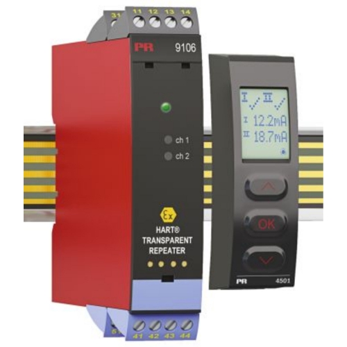
De PR Electronics 9106B is een 1- of 2-kanaals, geisoleerde 1:1 repeater barrier voor intrinsiek veilige toepassingen.
HART transparante repeater- 24 VDC-voeding via powerrail of connectoren
- Actieve en passieve mA-input
- Actieve of passieve output via dezelfde twee terminals
- Splitterfunctie - 1 in en 2 uit
- SIL3 Volledige beoordeling en gecertificeerde acc. volgens IEC 61508
- 9106B is een 1- of 2-kanaals geïsoleerde 1: 1-repeaterbarrière voor intrinsieke veiligheidstoepassingen.
- Het apparaat levert 2-draads SMART-zenders en kan ook worden gebruikt voor 2-draads SMART-stroombronnen. HART & BRAIN-protocollen worden ondersteund en worden bidirectioneel overgedragen.
- 9106B kan in het veilige gebied of in zone 2 / Cl worden gemonteerd. 1, div. 2 en ontvangen signalen van zone 0, 1, 2 en zone 20, 21, 22 inclusief mijnbouw / Klasse I / II / III, Div. 1, Gr. A-G.
- Voor duplicatie- / migratiedoeleinden kunnen de uitgangen naar twee verschillende DCS / PLC / HMI of andere bewakingssystemen worden verzonden.
- In veiligheidstoepassingen (SIL-loops) kan de 9106BxB worden gebruikt als een splitter met de volgende uitvoerconfiguratie:
- Bij gebruik van 9106BxB in een SIL2-veiligheidsfunctie, wordt kanaal 1 gebruikt voor de veiligheidslus. Kanaal 2 kan worden gebruikt voor elk niet-veiligheidsapparaat.
- Voor hogere veiligheidsdoeleinden (SIL 3), kan 9106BxB worden gebruikt als een splitter voor SIL 3-lussen. Kanaal 1 en 2 worden vervolgens verbonden met dezelfde veiligheids-PLC, waarbij kanaal 2 wordt gebruikt als een redundant diagnostisch kanaal. (raadpleeg voor meer informatie het FMEDA-rapport en de veiligheidshandleiding).
- Het afneembare PR 4501-display en de groene en rode LED's aan de voorzijde geven de status van elk kanaal aan.
- Bewaking van foutgebeurtenissen en kabelbreuk bij ingang via het individuele statusrelais en / of een collectief elektronisch signaal via de vermogensrail.
- Hoge galvanische isolatie van 2,6 kVAC.
- Snelle reactietijd <5 ms
- Hoge nauwkeurigheid beter dan 0,1%.
- 2-draads transmittervoeding> 16 V.
- De apparaten kunnen verticaal of horizontaal worden gemonteerd zonder afstand tussen aangrenzende apparaten.
-
Technical Details Environmental Conditions
Operating temperature
-20°C to +60°C
Storage temperature
-20°C to +85°C
Calibration temperature
20...28°C
Relative humidity
< 95% RH (non-cond.)
Protection degree
IP20
Installation in
Pollution degree 2 & meas. / overvoltage cat. II
Mechanical specifications
Dimensions (HxWxD)
109 x 23.5 x 104 mm
Dimensions (HxWxD) w/ 4501/4511
109 x 23.5 x 116 / 131 mm
Weight approx.
250 g
Weight incl. 4501 / 4511 (approx.)
265 g / 280 g
DIN rail type
DIN EN 60715/35 mm
Wire size
0.13...2.08 mm2 AWG 26...14 stranded wire
Screw terminal torque
0.5 Nm
Vibration
IEC 60068-2-6
2...13.2 Hz
±1 mm
13.2...100 Hz
±0.7 g
Common specifications
Supply
Supply voltage
19.2...31.2 VDC
Fuse
1.25 A SB / 250 VAC
Max. required power
≤ 1.1 W / ≤ 1.9 W (1 ch. / 2 ch.)
Max. power dissipation, 1 / 2 ch.
≤ 0.8 W / ≤ 1.2 W
Isolation voltage
Test /working: Input to any
2.6 kVAC / 300 VAC reinforced isolation
Analog output to supply
2.6 kVAC / 300 VAC reinforced isolation
Status relay to supply
1.5 kVAC / 150 VAC reinforced isolation
Response time
Response time (0...90%, 100...10%)
< 5 ms
Programming
PR 45xx
Signal dynamics, input
Analog signal chain
Signal dynamics, output
Analog signal chain
SMART bi-directional communication frequency range
0.5...7.5 kHz
Signal / noise ratio
> 60 dB
Accuracy
Better than 0.1% of sel. range
mA, absolute accuracy
≤ ±16 μA
mA, temperature coefficient
≤ ±1.6 μA / °C
Effect of supply voltage change on output (nom. 24 VDC)
< ±10 μA
EMC immunity influence
< ±0.5% of span
Extended EMC immunity: NAMUR NE21, A criterion, burst
< ±1% of span
Input specifications
Current input
Measurement range
3.5...23 mA
2-wire transmitter supply 9106B1x (Uo = 27.5 VDC)
>16 V / 20 mA
2-wire transmitter supply 9106B2x (Uo = 25.3 VDC)
>15 V / 20 mA
Sensor error detection: Loop break 4...20 mA
< 1 mA
Input voltage drop, supplied unit
< 4 V @ 23 mA
Input voltage drop, non-supplied unit
< 6 V @ 23 mA
Output specifications
Current output
Signal range
3.5...23 mA
Load (@ current output)
≤ 600 Ω
Load stability
≤ 0.01% of span / 100 Ω
Current limit
≤ 28 mA
Passive 2-wire mA output
Effect of external 2-wire supply voltage variation
< 0.005% of span / V
Max. load resistance [Ω]
(Vsupply-3.5)/0.023 A
Max. external 2-wire supply
26 VDC
Status relay
Relay function
N.C.
Programmable low setpoint
0...29.9 mA
Programmable high setpoint
0...29.9 mA
Hysteresis for setpoints
0.1 mA
Max. voltage
110 VDC / 125 VAC
Max. current
0.3 ADC / 0.5 AAC
Max. voltage - hazardous installation
32 VDC / 32 VAC
Max. current - hazardous installation
1 ADC / 0.5 AAC
of span
= normal measurement range 4...20 mA
Observed authority requirements
EMC
2014/30/EU
LVD
2014/35/EU
RoHS
2011/65/EU
EAC
TR-CU 020/2011
Approvals
ATEX 2014/34/EU
DEKRA 11ATEX0244 X
IECEx
DEK 11.0084X
FM
FM16US0465X / FM16CA0213X
INMETRO
DEKRA 16.0001 X
UL
UL 61010-1
EAC Ex TR-CU 012/2011
RU C-DK.GB08.V.00410
DNV-GL Marine
Stand. f. Certific. No. 2.4
ClassNK
TA18527M
CCOE
P337349/1
SIL
SIL 2 / SIL 3 certified & fully assessed acc. to IEC 61508
-
Documents:
Filename9106 Upload date Size 9106 Datasheet 2018.3.25 0.3 MB 9106 User Manual 2019.3.11 3.6 MB


